Ok, let's go to the advanced users zone

In our "before-the-stereopi" projects we used a lot of Raspberry Pis of all sizes (big size, A/A+ and Zeros). In most cases we were need to attach a high power consuming devices (long-range WiFi dongles etc.). And we faced a problem with power management on a Pi. Almost always we used soldering to the pads on the bottom part of the Pi to connect power directly to the USB devices.
fraserbarton wrote: Sun Oct 06, 2019 12:12 pm
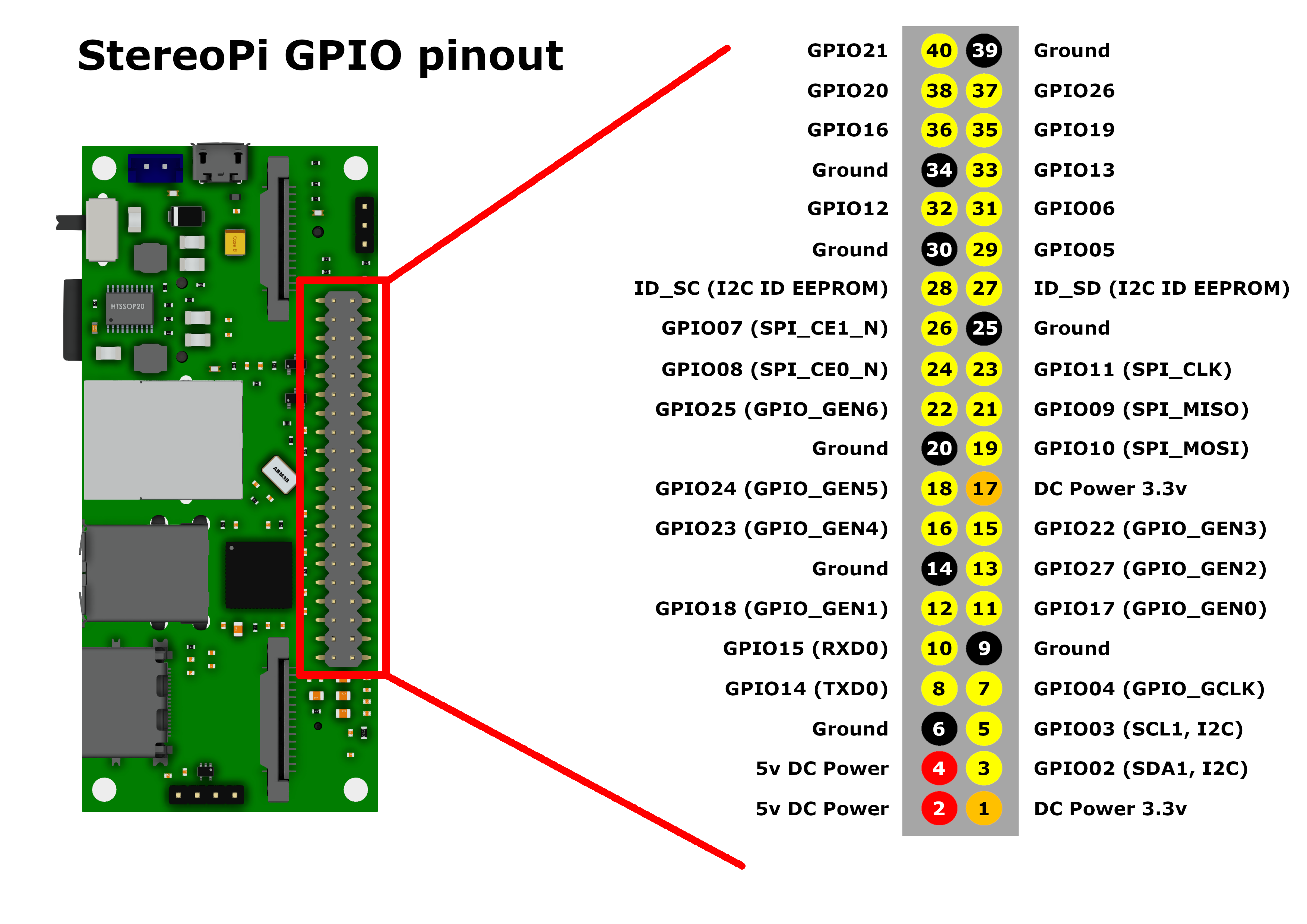
Having looked at the schematics it seems that the 2 pin power header and pin 2 and 4 on the GPIO header are directly connected when the switch is closed as you say.
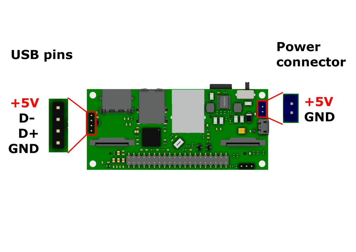
That's why in the StereoPi we implemented direct power schematics. It means power goes directly from your power source to the power lines of USB connectors and GPIO pins, without any control from Broadcom's SoC side.
So we suggest that advanced users will be glad to find this solution and use it in their projects. That is having a BEC on your drone you can use several ways to power-up StereoPi-based solution.
fraserbarton wrote: Sun Oct 06, 2019 12:12 pm
Do you have any input with regards to that? Don't worry if not as I can't see myself resisting the urge to just power straight through the GPIO header.
To say briefly, the most power-sensible element is RPi Compute Module. That is, ideally, you need to provide 5V (+/- 0.5V) without any aggressive noise and drawdowns. For example, if you use LiPo battery with insufficient current for your copter, and while aggressive fly your power voltage (BEC or other converter) will go to 4V or lower, CM3 will reboot. The second element - your USB devices. Taking two these points into account will help you to understand, if your powering approach is correct.
Eugene a.k.a. Realizator